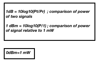
RF measurements are performed in dB (decibels )and not in mW since it is difficult to perform calculations on smaller mW values of wireless power. Due to this reason, change in RF power is expressed as logarithmic functions of power values.
dBi – measurement of antenna gain relative to theoretical isotropic antenna gain dBd – measurement of antenna gain relative to the dipole antenna gain

Rule of 3s and 10s
* Gain in 3dB of power will double the power in mW
* Loss in 3dB of power will half the power in mW
* Gain in 10dB of power will increase power in mW by 10 times
* Loss in 10dB of power will decrease power in mW by 10 times
Example: 8dBm of power can be written as 10 + 10 – 3 – 3 – 3 – 3 in dBm
Using this rule, we can write the above step as (10*10) /(2 *2*2*2) = 6.2 mW of power.
6dB rule
* Gain in 6dB of signal power will double coverage of RF signal
* Loss in 6dB of signal power will half coverage of RF signal
Receiver Sensitivity is the lowest signal strength or the weakest signal that can be successfully received at the receiver.
Device with receive sensitivity of -70 dBm could hear/decode signal better than the device with receive sensitivity of -65 dBm.
Free Path Loss
Loss of RF signal from transmitter antenna to receiver antenna and not including the antenna gain due to the natural broadening of signals known as beam divergence is called Free Path Loss (FPL). It is based on distance (d) between Tx and Rx antenna and the frequency (f) in which the signal operates (in MHz)

Fade Margin
It is the extra buffer or desired level of signal above the receiver sensitivity of the receiver that is determined during link budget calculations to accommodate any fluctuations in received RF signal due interferences such as weather and other factors. Usually, use of fade margin of 10 to 25 dB is observed in most of the networks. This is similar to SOM where the latter is measured once the RF link is installed based on determined fade margin and link budget calculations.
System Operating Margin (SOM)
The represents the amount of received signal strength (S) relative to the receiver sensitivity of the receiving Wi-Fi device (RS) in dBm.

Link Budget is a measurement of RF energy between two transceivers for the formation of successful link communication for a given setup. This calculation should consider transmit power, cable and connector losses, antenna gain on either side along with free space path loss.
Steps performed during link budget calculations:
- Determine the Received Signal strength
- Determine the SOM
Example
Perform link budget calculations for the communication link between two Wi-Fi transceivers and examine their reliability. One of them is connected to the antenna with 10 dBi gain, with a transmitting power of 100 mW and a receive sensitivity of -84 dBm. The other end is connected to an antenna with 13 dBi gain, with a transmitting power of 16 dBm and a receive sensitivity of -82 dBm. The cables in both systems are short, with a loss of 2dB at each side at the 2.4 GHz frequency of operation.
1. Calculation of free path loss during transmission of RF signal
Free Path Loss = 32.4 + 20log 10 (f) + 20log 10 (d)
FPL = 32.4 + 20log 10 (2400) + 20log 10 (10)
FPL = 32.4 + 87.6 = 120 dB
d is distance between AP and client in km = 10
f is RF operating in MHz= 2.4GHz = 2400 MHz
2. Calculation of link margin from AP to the client
Received Signal strength of client = (Tx power of AP)+ (antenna gain + all power loss on either side) + FPL
Tx Power at AP = 100 mW = 10log 10 (100) = 20 dBm
Antenna gain of AP = 10 dBi
Antenna gain of client = 13 dBi
Cable RF losses on either side= 2dB X 2 = 4 dB
Received signal strength (S)= 20 + 10 + 13 – 4 – 120
= -81 dBm
Receive Sensitivity (RS) of the client = -82 dBm
Link Margin (SOM) = S – RS
= -81 – (-82) = 1 dB
The link from first station to the second station will work since the received signal strength is greater than the receive sensitivity; though it cannot be considered reliable since the fade margin is only 1 dB It is recommended to have at least 10 dB to avoid any external interferences like changing weather conditions and other factors.
3. Calculation of link margin from client to AP
Received Signal strength at AP= (Tx power of client) + (antenna gain + all power loss on either side) + FPL
Tx Power at client = 16 dBm
Antenna gain of AP = 10 dBi
Antenna gain of the client = 13 dBi
Cable RF losses on either side = 2dB X 2 = 4 dB
Received signal strength (S)= 16 + 10 + 13 – 4 – 120
=-85 dBm
Receive Sensitivity (RS) of the AP = -84 dBm
SOM = S – RS
= -85 – (-84) = -1 dB
Conclusion: Link from client to the AP is definitely not reliable since the received signal strength at the AP is less than the receive sensitivity of the AP.
**Please note that there is an error in link budget calculation for CWDP-302 question in pg. 260 that is clarified by CWNP team in the below post:
https://www.cwnp.com/forums/posts?Link-budget-confusion-119061
RF Line of Sight
RF line of sight is like the visual line of sight that are required for RF communications over long distances. This is not always a straight line and is highly susceptible to interferences.
The infinite number ellipsoidal areas around RF line of sight are called Fresnel Zones. The first fresnel zone or 1FZ that lies closest to the RF line of sight should be the most impacted zone for a WLAN link.
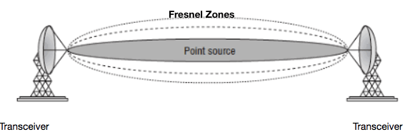
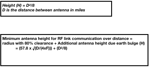
It is important to calculate the radius of 1 FZ to determine the minimum height of the antenna to have a successful RF line of sight for the WLAN communications.
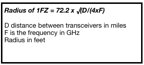
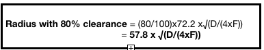
As a WLAN designer, it is better to choose a clearance radius of 1 FZ of at least 80%, which means that there could be a blockage of 20 %. This value is based on the growth of certain trees that could block the 1 FZ.
Besides this, it is important to consider the earth bulge for determining the additional height of the antenna in feet.
RF Online Calculators:
https://www.everythingrf.com/rf-calculators/link-budget-calculator
References:
CWDP-302
CWNA – 105
